- Ningbo Dongning Tools Co.,Ltd
- Professional Chinese Tools manufacturer on automotive speciality tools,bearing puller&heavy truck tools
- Address
- No.6 Falan Rd,Hengjie Town,Ningbo City,Zhejiang,China
- Phone
- +86-574-87216625
- info@nbdntools.com

Transmission gear and bearing removal tools must be selected around contact geometry, clearance, and the specified force path. The aim is controlled separation of the fitted part while protecting the shaft, gear faces, housing, and replacement components.
A gear with a usable hub, a bearing on a shaft, and a component recessed in a case do not use the same fixture. Confirm the part to be removed and follow the model-specific teardown sequence.
Snap rings, lock plates, staked features, fasteners, and specified heat procedures can prevent removal. Recheck the service procedure before adding force to any fitted component.
Use a jaw puller only where the jaws can engage a strong, balanced surface without touching teeth or thin flanges. Keep the puller centered so the gear comes off squarely.
A bearing separator is often the safer choice when there is little space behind an inner ring. Pair it with a bridge or puller arrangement that supports both sides evenly.
A press may be appropriate when the transmission is disassembled and the correct race or hub can be supported. Never press through a bearing path that is not intended to carry installation or removal force.
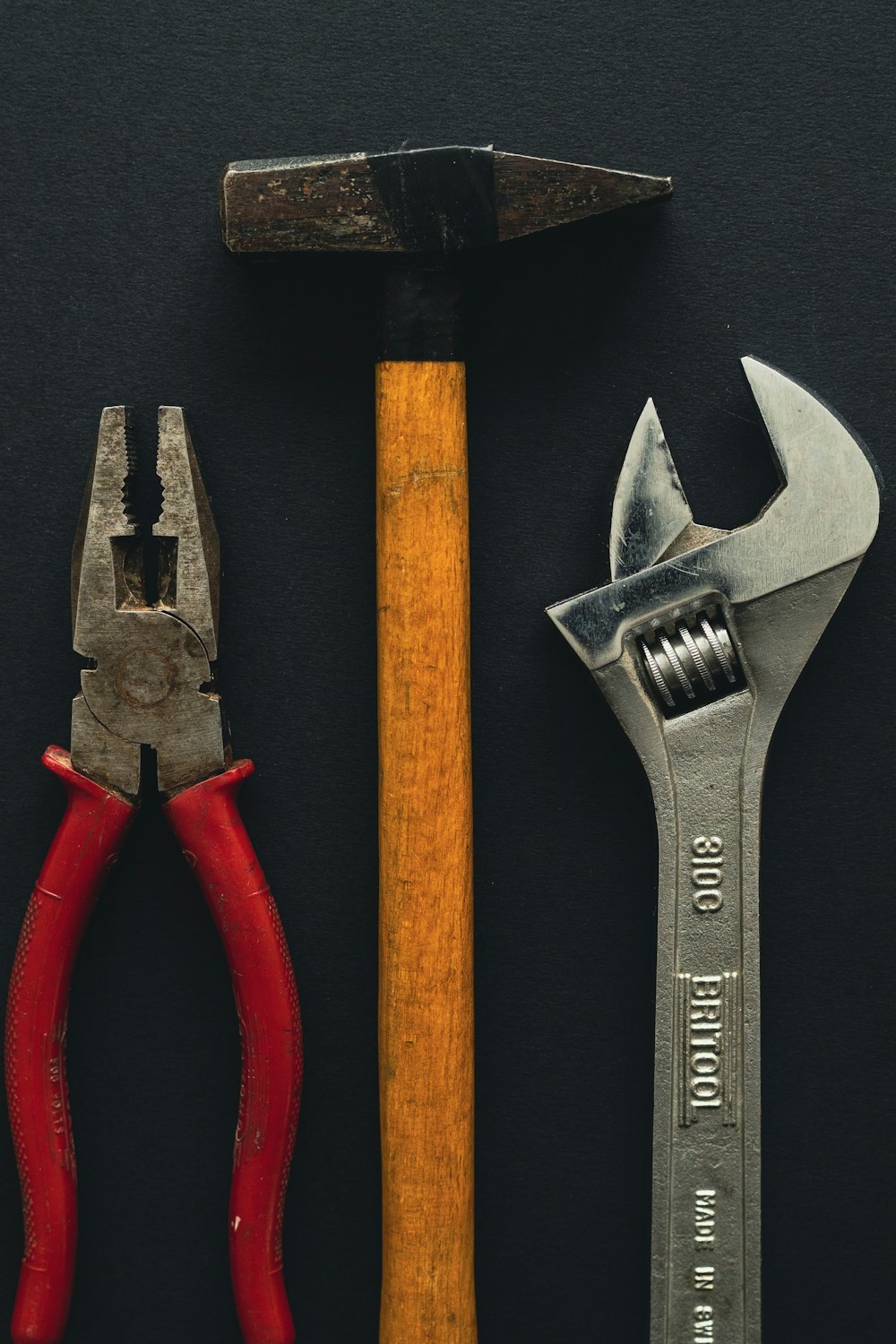
Adapters and sleeves should contact a robust, intended surface and fit the diameter closely. Improvised spacers can slip, tilt the assembly, or concentrate force on a precision edge.
Align the forcing screw, separator bridge, or press ram with the shaft centerline. Stop and reset if the component begins to tilt, the fixture shifts, or extraction resistance changes unexpectedly.
For tight fits, use rated hydraulic equipment only with a stable fixture, protective barriers, and a clear exclusion area. Increase force gradually and do not exceed the lowest-rated component in the setup.
After removal, examine seats, splines, shoulders, and grooves. Plan the installation method separately so force is applied only to the correct bearing race or component surface; DNT Tools can assist with a practical tool list.
Need a puller setup matched to your shaft, bearing, and access dimensions? Contact DNT Tools with the component details and available clearance.