


- Ningbo Dongning Tools Co.,Ltd
- Professional Chinese Tools manufacturer on automotive speciality tools,bearing puller&heavy truck tools
- Address
- No.6 Falan Rd,Hengjie Town,Ningbo City,Zhejiang,China
- Phone
- +86-574-87216625
- info@nbdntools.com

The axle nut is loosened while the car is on the ground. The vehicle is raised, the wheel and brake caliper moved out of the way, and the axle nut is removed. The front hub bolts are removed and the hub is pried away from the steering knuckle. The ABS sensor wire is disconnected and the new hub is installed.
Replacing The Front Wheel Bearings and Hub
placed wheel chocks on both sides of the tire and used a big flat screwdriver to remove the hub cap.
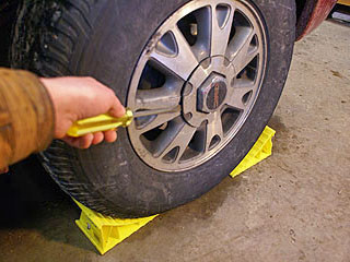
1/2" drive impact 36mm axle nut socket is deep enough to accommodate the part of the axle that sticks out beyond the hub nut.
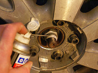
apply some penetrating oil to the axle threads in front of the hub nut.
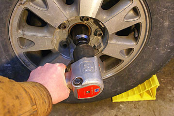
put the socket on impact wrench and tried loosening the axle nut. It's not sure if the impact wrench would be able to remove this nut, but within a couple of seconds the nut had rotated a quarter-turn.Sometimes it's hard to see the impact socket turn, so used a permanent marker to mark the top of the hub nut. That way you could just pull the socket away and see how much the nut had turned.
Then raised the front end and supported the car on jack stands.and removed the wheel with my impact wrench and a 3/4" impact socket.
warring: If an impact wrench is not available, the lug nuts must be loosened before the car is raised. Otherwise the wheel will rotate when the lug nuts are turned.
Unbolting The Brake Caliper:
The brake caliper needs to unbolted and hung safely out of the way with mechanic's wire or bungee cords.
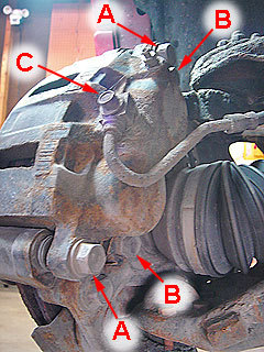
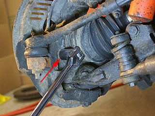
There are several fasteners on the back side of the brake caliper.Only the brake bracket mounting bolts (B) need to be removed for this repair. removed these bolts with an 18mm box-end wrench.In case you are curious... The bolts marked "A" are the caliper slide pins. "C" points to the brake line connector.
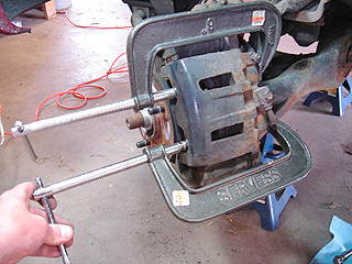
Before lift the caliper and bracket off the steering knuckle, must push the caliper back with a big 6" C-clamp, similar to what is shown in this picture. This picture is from our article about replacing front brakes on this 1999 Jimmy, which provides more details about working on the front brakes.
used a 34" long bungee cord to support the caliper. The bungee cord is wrapped around the shock absorber tower. A bungee cord about 3 to 6" shorter would've worked even better.It's important to make sure that the caliper does NOT simply hang on the flexible brake line. That can damage the brake line.
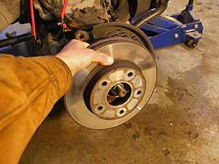
removed the brake disc (rotor). It simply slid off, but sometimes the rotor can be stuck to the hub from corrosion. In that case it may be necessary to tap the rotor carefully with a hammer.
Then removed the hub nut with the impact wrench and 36mm socket. This nut did not spin easily... I'm guessing that they designed the threads so the nut would be self-locking.There was a big flat washer behind the hub nut, which I removed.

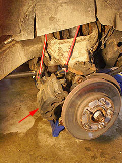
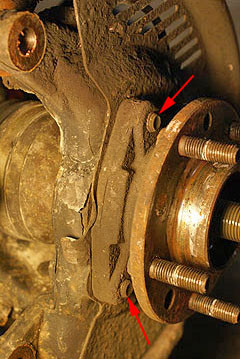
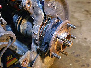
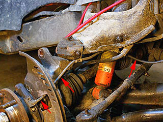
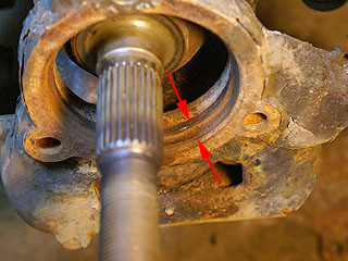
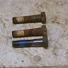
There are 3 bolts that secure the hub to the steering knuckle. The heads of the bolts are towards the inside of the vehicle... the ends of two of the bolts (red arrows) are visible here.sprayed some penetrating oil on the ends of the 3 bolts.
turned the steering wheel to gain access to the top and rear bolt heads.
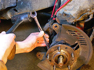
To remove the hub mounting bolts, used a "poor man's impact wrench", which is simply a box-end wrench (18mm in this case) and a dead-blow hammer to pound on the end of the wrench.Given that these bolts are supposed to be tightened to 133 foot-pounds
Then turned the steering wheel the other way to expose the front mounting bolt.
used an 18mm socket on a 1/2" drive breaker bar to loosen this bolt.Once the bolt was loosened, use a ratchet with a 2-1/4" extension to remove the bolt. Without an extension the head of the ratchet wouldn't fit next to the CV joint.These bolts didn't unscrew very easily because they had thread-locker compound on them.
Note that some GM trucks and SUV's may use 4 bolts to fasten the hub to the steering knuckle and the removal procedure may be different.
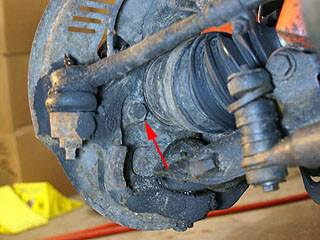
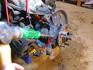
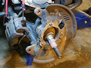
To separate the hub from the steering knuckle, I hammered a screwdriver between the hub and the knuckle (arrow).This is not an ordinary screwdriver... I call it a beatin' screwdriver, which has a shaft that goes all the way through the head, and a metal cap on the end. If I used a normal screwdriver with a plastic handle (and no metal cap on the end) the handle would just break.These are cheap screwdrivers... many years ago I bought several for less than a buck each.
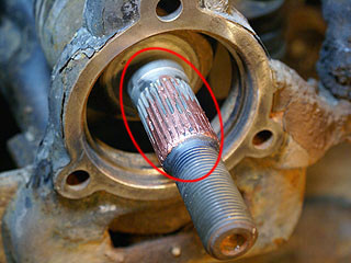
With a little more prying (and tapping on the end of the axle shaft) the hub completely separated from the steering knuckle.However, the center of the hub was still attached to the axle (the shaft has splines that engage the center of the hub). sprayed some penetrating oil into the splines around the shaft, just beyond the ends of the threads.
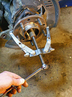
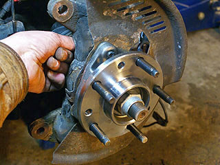
used 2-jaw 4-inch gear puller to pull on the hub while pushing the axle inward.
Disconnecting The ABS Sensor Wire:
The new wheel hub assembly included the ABS (anti-lock brake system) sensor and a long wire with a connector.
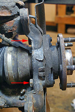
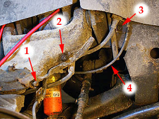
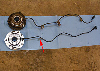
The ABS sensor has a long wire that runs into the engine compartment. The arrows point to the ABS wire.There were three brackets to remove.
1: The mounting location of the first bracket (which I had already removed). This required a 10mm socket.
2: Second bracket, which required a 13mm wrench to hold the bolt head on the inside of the upper control arm, and a 13mm wrench (or socket) to remove the nut.
3: Third bracket, which required a 13mm socket.
4: ABS sensor wire.Brackets 2 and 3 needed to be re-used. The new hub includes bracket 1.
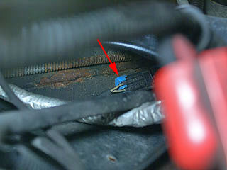
The ABS sensor wire connector (arrow) is barely visible in this picture.This is located in the engine compartment, below and to the right of the battery (when viewed from the front).
Once the ABS wire was released, I pulled the hub off the axle.handled the axle carefully, making sure not to damage the splines or the rubber boot around the CV joint.
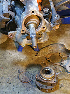
One possible source of grief: There is a lip around the circular opening, and the hub fits inside this lip. But there was some rust on this surface, and figured this could create some interference when the new part is installed.
removed the rust with the tip of a file, by scraping around the rim in a circular motion. Then blew the dirt out with compressed air and a blow gun. cleaned the dust from the axle splines with a paper towel and brake parts cleaner.
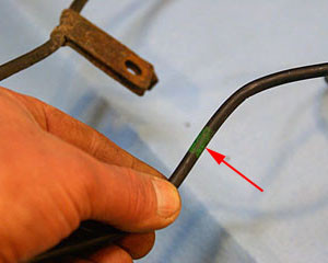
The new hub assembly came with the ABS sensor and wire. It also included 1 of the 3 brackets needed (arrow).The instructions say that the old sensor cannot be re-used because it's not compatible with the new hub. The second and third brackets need to be installed on the wire on the new hub.
There were green marks on the new wire where the old brackets needed to go.
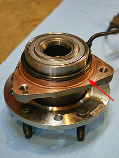
Before installing the new hub, I applied a thin coating of copper-based anti-seize compound around this part of the hub, where the hub fits tightly into the steering knuckle.
apply some anti-seize to the splines on the axle. This should make these parts easier to remove in case and to remove the bearing or axle later.It's possible that a constant-velocity (CV) joint may need to be replaced someday, and this connection would need to be taken apart.
used a wire wheel to clean up the threads on the hub mounting bolts.The white stuff on the bolts is probably some type of thread-locking compound. apply some medium-strength thread-locker to the cleaned-up bolts.
Installing The New Hub:
remove the hub bolts and put the guard in place. then install the splash guard
Installing the new hub wasn't easy because the axle sprung outward when the old hub was removed.
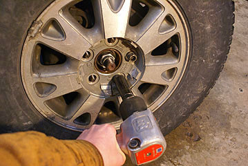
Then used the impact wrench and 36mm socket to tighten the hub nut most of the way.
Next attached the cable brackets to the car. The second bracket was kinda tricky... put the bolt through the hole in the bracket and then push the bolt through the brake hose bracket and through the upper control arm.
Connecting the electrical connector was a total hassle. There was only enough space to get one hand down there. After a lot of struggling I finally got the wires connected.
Then replace the brake rotor and brake caliper. Before putting the rotor back on, tightened the brake bracket mounting bolts with an 18mm wrench. These bolts need to be pretty tight, probably similar to the 133 foot-pounds required for the hub mounting bolts.
replaced the wheel and lowered the car. Then tightened the wheel lug nuts with a torque wrench to 100 foot-pounds, chocked the wheel again and put the 36mm socket on my torque wrench. The scale on the wrench only goes up to 150 foot-pounds, and the torque requirement in 165. turned the dial another one-and-a-half turns and tightened the axle nut until the wrench clicked. Just to be sure, used the impact wrench to turn the axle nut another 10 to 15 degrees.
replaced the hub cap and took the car for a test drive.