product Instruction:9 Liter Capacity Manual and Pneumatic Fluid Extractors
9 Liter Capacity Manual and Pneumatic Fluid Extractors
9Ltr Capacity device constructed from composite materials
Uses compressed air supply to generate vacuum
Suitable for the extraction of all types of engine, transmission, and lubricating oils
Suitable also for low-viscosity fluids such as water
Uses probes to extract engine oil through the dipstick tube
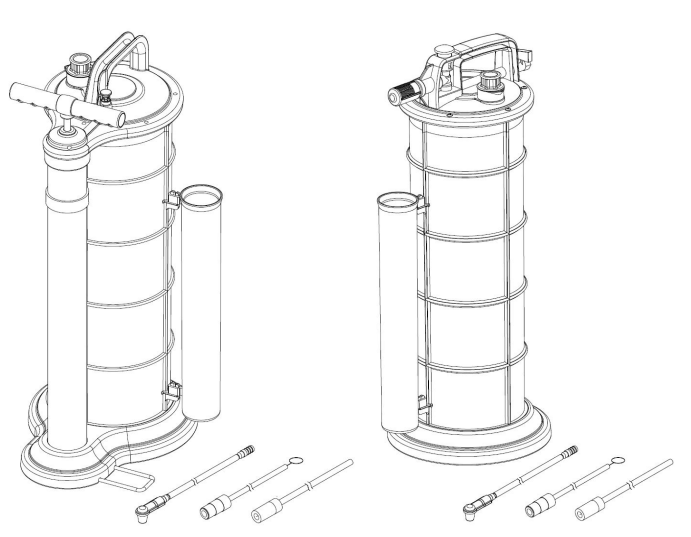
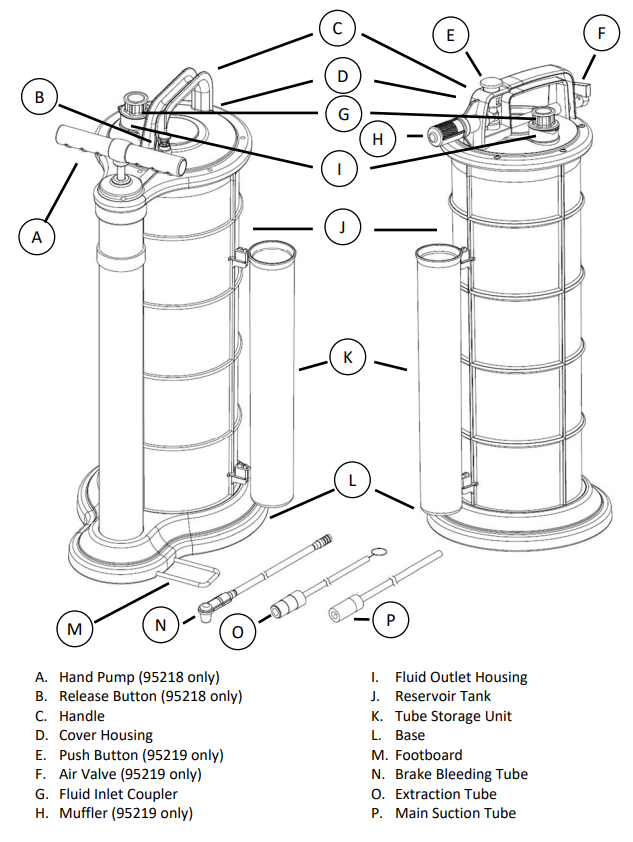
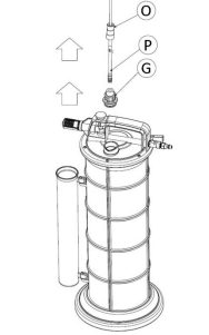
Part Nomenclature
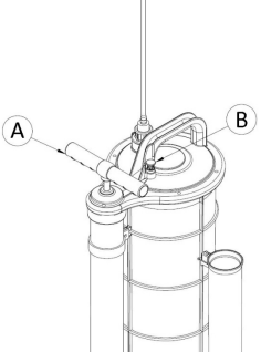
A. Hand Pump (95218 only)
B. Release Button (95218 only)
C. Handle
D. Cover Housing
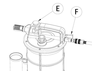
E. Push Button (95219 only)
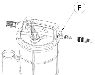
F. Air Valve (95219 only)
G. Fluid Inlet Coupler
H. Muffler (95219 only)
I. Fluid Outlet Housing
J. Reservoir Tank
K. Tube Storage Unit
L. Base
M. Footboard
N. Brake Bleeding Tube
O. Extraction Tube
P. Main Suction Tube
Instructions for Use - Oil Extraction
1. Park vehicle on level surface and apply vehicle’s emergency brake.
2. Start the engine and idle the vehicle until it reaches normal operating
temperature. Shut engine off.
3. Remove engine oil dipstick from the vehicle.
4. Insert Extracting Tube (O) into the dip stick hole until it reaches the
bottom of the oil pan.
5. Insert Main Suction Tube (P) into Fluid Inlet Coupler (G).
6. Connect Main Suction Tube (P) to Extracting Tube (O) using the Extracting
Tube adapter (rubber coupler).
7. Make sure Air Valve (F) is in the closed position (perpendicular to inlet hose). Connect the air hose to the Air Valve and turn on the air compressor.
8. Turn Air Valve Switch (F) to the open position (¼ turn clockwise) and press the Push Button (E).
9. When the Reservoir Tank (J) is full, the extractor will automatically shut off. If extractor does not become completely full, turn Air Valve (F) to the off position in order to stop the extractor. Proceed to Step 12.

10. Lift Handle (A) to top position and
return back to bottom position. Repeat
this pumping action to create vacuum
in the Reservoir Tank (J). Oil will begin
extracting into Reservoir Tank (J).
11. When oil in Reservoir Tank (J) reaches
“full” position, the Handle (A) of the
hand pump will become difficult to
depress due to back-pressure in the
Reservoir Tank. Press the Release
Button (B) to return the Handle (A) to its bottom position.
12. Disconnect Extracting Tube (O) and Main Suction Tube (P) from Fluid Inlet Coupler (G).
13. Remove Extracting Tube (O) from dip stick hole.
14. Remove Fluid Inlet Coupler (G) from Fluid Outlet Housing (I).
15. Dispose of fluids in accordance with the laws and regulations of your state.
Instructions for Use – Brake Bleeding
Before Bleeding Brakes
Bleed brake system in following order:
1. Master cylinder (if necessary)
2. ABS controller (if necessary)
3. Wheel cylinders and calipers in manufacturer recommended order.
Bleeding Brakes
1. Park vehicle on level surface and apply vehicle’s emergency brake.
2. Make sure master cylinder reservoir is full of manufacturer specified brake fluid and more new fluid is available to top off reservoir during
bleeding procedure. Also be sure to clean off bleeder fittings before beginning bleeding procedure.
3. Remove bleeder fitting cap and place wrench on the nut of the bleeder screw.
4. Connect Brake Tube w/ Rubber Fitting (N) to vehicle’s bleed screw. (Note: Refer to manufacturer’s manual for proper bleed order. Typically, you should bleed brakes from farthest from master cylinder to closest.)
5. Insert Main Suction Tube (P) into Fluid Inlet Coupler (G).
6. Connect Main Suction Tube (P) to Brake Bleeding Tube (N).
7. Make sure Air Valve (F) is in the closed position. Connect the air hose to the Air Valve and turn on the air compressor.
8. Turn Air Valve (F) to the open position and press the Push Button (E).
9. Open the bleeder screw slightly, just enough to cause fluid to flow into the Brake Bleeding Tube (N).
10. Evacuate fluid until no air bubbles are present in the clear tube and then tighten the bleeder screw.
11. Top off master cylinder reservoir and proceed to next brake according to manufacturers bleeding order. Repeat until bleeding of all brakes has been completed.
12. When the Reservoir Tank (J) is full, the extractor will automatically shut off. If extractor does not become completely full, turn the Air Valve (F) to the off position in order to stop the extractor. Proceed to Step 18.
Steps 13-17 are for Manual Extractor only.
13. Open the bleeder screw slightly, just enough to cause fluid to flow into the Brake Bleeding Tube (N).
14. Lift Handle (A) to top position and return back to bottom position. Repeat this pumping action to create vacuum in the Reservoir Tank (J). Brake fluid will begin transferring into Reservoir Tank (J).
15. Evacuate fluid until no air bubbles are present in the clear tube and then tighten the bleeder screw.
16. Top off master cylinder reservoir and proceed to next brake according to manufacturers bleeding order. Repeat until bleeding of all brakes has been completed.
17. When brake fluid in Reservoir Tank (J) reaches “full” position, the Handle (A) of the hand pump will become difficult to depress due to backpressure in the Reservoir Tank (J). Press the Release Button (E) to return the Handle (A) to its bottom position.
Steps 18-20 are for both Manual and Pneumatic Extractors.
18. Disconnect Extracting Tube (O) and Brake Bleeding Tube w/ Rubber Fitting (N) from Fluid Inlet Coupler (G).
19. Remove Brake Bleeding Tube (N) from bleeder fitting.
20. Remove Fluid Inlet Coupler (G) from Fluid Outlet Housing (I). Properly dispose of fluids in accordance with the laws and regulations of your state.
21. Rinse the Reservoir Tank after finishing with the extractor.